


Introduction
The Samsung Medical Center (SMC) was founded on November 9, 1994 under the philosophy of "contributing to improving the nation's health through the best medical service, advanced medical research, and development of outstanding medical personnel." SMC consists of a hospital and a cancer center; the hospital is located in an intelligent building with 20 floors above ground and 5 floors underground, housing 40 departments, 10 specialist centers, and 120 special clinics. The cancer center has 11 floors above ground and 8 floors underground. SMC is a tertiary hospital manned by approximately 7,400 staff including over 1,200 doctors and 2,300 nurses.
The Proton Therapy Center at SMC will be the first private-hospital based proton therapy center in Korea. Although there still exist some debates on the cost-effectiveness of the proton therapy, the well-proven superior dosimetric properties of the proton therapy leads to an increasing number of proton therapy facilities around the world [1].
SMC will introduce the state-of-the-art proton therapy system, and by introducing the most advanced radiation therapy system, SMC expects improved treatment outcomes with minimal toxicity and improved quality of life of patients.
The Proton Therapy Center at SMC is located in a new building on the land area of more than 150,000 m2 with floor space of more than 14,000 m2 (6 floors above ground and 4 floors underground). The computed tomography (CT) and magnetic resonance imaging devices will be installed in the Proton Therapy Center so that both diagnostic imaging and proton beam treatment can be conducted in the same building.
After the contract is signed with Sumitomo Heavy Industries Ltd. (hereafter SHI), the groundbreaking ceremony of the proton therapy center was in October 2011 and the machine installation started in May 2013.
The proton therapy system at SMC (SMC-PTS) will have distinguished characteristics with the state-of-the-art technologies like, image-guided proton therapy with cone-beam computed tomography, respiratory gated proton therapy, accurate patient positioning with a robotic couch, and an effective treatment preparation with multi-leaf collimator (MLC).
This report provides an overview of the status of the SMC-PTS focusing on the major equipment used for the acceleration, transport, and delivery of proton beams. The clinical commissioning of the SMC-PTS systems, dosimetric measurements and calculations will be described in future publications.
Materials and Methods
1. The SMC proton therapy system
1) The overall proton therapy system
The SMC-PTS can be divided into following subsystems: the proton beam generator, irradiation system, patient positioning system, patient position verification system, respiratory gating system, and operating and safety control system.
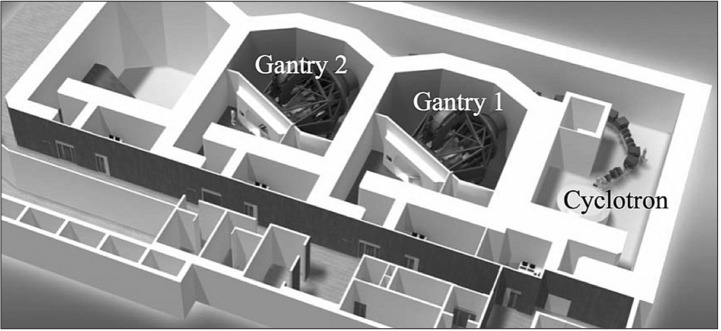
The proton beam generator includes the accelerator, energy selection system (ESS), and beam transport system (BTS). And the irradiation system is composed of a rotating gantry and a nozzle. Each of the treatment rooms has its own irradiation system (a multi-purpose nozzle or a dedicated scanning nozzle). Details of each subsystem will be described in following sections and the layout of the treatment level of the Proton Therapy Center at SMC is shown in Fig. 1.
2) Proton beam generator
The proton accelerator at SMC-PTS is a normal conducting azimuthally varying field (AVF) cyclotron. The magnetic field strength in the cyclotron is designed to be radially increasing to correct the increased relativistic mass of accelerated protons. At the same time, the vertical defocusing of the protons due to the radially increasing magnetic field is adjusted by the azimuthally varying magnetic field configuration (hill and valley structures). The magnetic field of the cyclotron ranged from 0.9 T (valley) to 2.9 T (hill). The diameter of the cyclotron is 4.3 m and the weight of the cyclotron is approximately 220 tons.
The accelerator is composed of electromagnet system, radio frequency (RF) system, ion generator, and beam extractor. The electromagnet system generates a magnetic field inside the cyclotron and the RF system accelerates protons at a high frequency (106 MHz). There are two RF cavities located in the cyclotron. The ion generator ionizes hydrogen gas molecules in plasma state and generates protons to be accelerated in the cyclotron. In the beam extractor, the deflector applies a high voltage to deflect protons toward the outer extraction orbit using an electric field. After the deflector, the proton beams are focused by a pair of permanent quadrupole magnets. The cyclotron accelerates protons up to the energy of 230 MeV.
The ESS is composed of an energy degrader, an energy analyzer electromagnet, and a beam diagnosis system. The energy of proton beam can be adjusted by the thickness of the degrader in the range of 70 MeV to 230 MeV.
Although the extracted proton beams from the cyclotron are highly focused by the pair of permanent quadrupole magnets in the cyclotron, the energy width and emittance of proton beams will be increased by the degrader material. In the downstream of the degrader, the ESS composed of a set of quadrupole magnets and a bending dipole magnet deflected at an angle of 30° is located to re-focus the beam and select the proton beams only in the defined energy window by using a copper beam slit.
After the ESS and BTS is located to deliver and distribute proton beams to each treatment room. The BTS consists of a series of quadrupole electromagnets for beam focusing, bending dipole magnets for changing beam direction, and steering magnets for fine-tuning of the beam paths to the treatment rooms. It also includes profile monitors and beam current monitors.
3) Irradiation system
Both treatment rooms have isocentric gantries, which are rotating steel structures that include the irradiation nozzles. The maximum radius of the gantry is 5.3 m and the mass of rotating part is 120 tons. The gantry rotates ±180° with 5° over-travel around the patient with the maximum rotation speed of the gantries is 1 rpm. The gantry system has the braking system equipped with 6 air-operation brakes. The 6 brakes assure an emergency stop within 5° at the maximum rotation speed.
Treatment nozzles are located at the end of the treatment room beam-lines and consist of various components to amend beam characteristics for clinical uses. There are two types of nozzle systems installed at SMC-PTS: a multi-purpose nozzle and a dedicated scanning nozzle. The multi-purpose nozzle has both wobbling and scanning function with corresponding nozzle components alignment. The dedicated scanning nozzle has a helium gas filled pipe, which minimizes unwanted interactions of proton beam in the beam path.
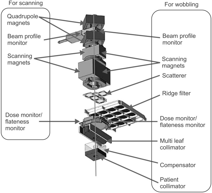
Multi-purpose nozzle
The multi-purpose nozzle installed at the first gantry room provides both wobbling and scanning modes. The components of the multi-purpose nozzle are focusing quadrupole magnets, beam profile monitor, wobbling (scanning) magnets, scatterers, ridge filters, dose monitor, flatness monitor, MLC, a patient-specific compensator, and patient collimators as shown in Fig. 2. The beam profile monitor in the upstream of the nozzle is inserted in wobbling mode. Scatterers and ridge filters will be used only for wobbling mode. The maximum field size of the nozzle in wobbling mode is 25 cm × 25 cm with MLC retracted (20 cm × 20 cm with MLC), and 24 cm × 24 cm in scanning mode. The maximum range without a scatterer is 32 g/cm2 and the range can be adjusted in steps of 0.1 g/cm2
Dedicated scanning nozzle
The dedicated scanning nozzle is installed at the second gantry room with a helium gas filled pipe. The maximum field size of the dedicated scanning nozzle is 30 cm × 40 cm which is larger than the maximum field size of the multi-purpose nozzle. As shown in Fig. 3, quadrupole magnets, beam profile monitor, scanning magnets, helium gas filled pipe, dose monitor, flatness monitor, and optional patient collimator are the main components of the dedicated scanning nozzle. As for the dose painting, a line-scanning method that is faster than spot scanning will be implemented in the scanning control system.
4) Patient positioning system and patient position verification system
The patient positioning system consists of a robotic couch (Forte Automation Systems Inc., Machesney Park, IL, USA) and laser markers. One of the laser markers is located on the nozzle so that the center of the proton beam flux can be marked. There are additional laser makers located in the enclosure (horizontal) and the ceiling (vertical) to mark the isocenter. The robotic couch is composed of a table unit and a tabletop. The table unit has 6° of freedom and equipped with load cells for collision detection and deflection compensation. The robotic couch can support the maximum weight of 200 kg.
The VeriSuite (MedCom, Darmstadt, Germany) patient position verification system is composed of two orthogonal X-ray imaging systems. Each of the X-ray imaging system includes an X-ray generator, an X-ray imaging panel, and an image-processing device. Neither of the X-ray imaging axes are aligned with the proton beam axis as the X-ray imaging beam axis is off by 45° from the beam axis. The VeriSuite system can be operated in 3 different image acquisition modes: digital radiography (DR), fluoroscopy with respiratory signals, and cone beam computed tomography (CBCT). The acquired images will be compared with planning CT images and a correction vector will be calculated for a precise patient positioning.
5) Respiratory gating system
At SMC-PTS, AZ-733V (Anzai Medical, Tokyo, Japan) system is installed for gating of a respiratory motion. The system is mainly composed of a respiratory sensor (RS), a sensor port (SP), and a wave deck (WD). The RS detects abdominal motions (pressure changes) of a patient and the SP amplifies and transmits the analog signal from RS. The WD receives the signal from the SP and converts the signal to digital so that it can be sent to a personal computer.
The respiratory gating system should be installed not only in the irradiation system but also in the simulation CT system in order to take images synchronously with a patient's respiration. An identical AZ-733V respiratory gating system will be implemented in Discovery CT590 RT (GE Healthcare, Milwaukee, WI, USA) located in the simulation room.
6) Operating and safety control system
As the proton therapy system is composed of many different devices, the control of the whole system can be more efficient if the system is segmented into several groups. The segmentation can be performed according to function, procedures, and location. At SMC, the proton therapy system is mainly divided into two groups: the accelerator group and the treatment group. The accelerator group includes the proton beam accelerator, the ESS, and BTS. The treatment group includes the irradiation system, the patient positioning system, and the patient position verification system. Two groups meet at the exit of the bending magnet in the gantry. The operation of two groups is physically separated at different locations, the accelerator control room and the treatment control room.
The main control system is composed of encoders connected via a network to control both groups. Under normal operation, oncology information system is in operation connected with the control system.
A treatment safety unit is connected to each control unit of the proton therapy system via DeviceNet network, and the treatment safety unit is also connected to the door interlock system, the emergency stop buttons, and the radiation dose monitor system. The treatment safety unit controls overall safety of the system operation.
2. Monte Carlo simulation
We have used TOol for PArticle Simulation (TOPAS) for the Monte Carlo simulation of the treatment nozzle system. TOPAS [2] has been developed mainly for the Monte Carlo simulation of particle therapy nozzles based on Geant4 framework [3]. Participating in the α-version development, SMC has developed the model of SHI system and the developed modules (generic MLC and ridge filter) have been included in TOPAS package. The specific geometry of treatment nozzles has been provided by SHI in the agreement of using the developed Monte Carlo simulation in commissioning.
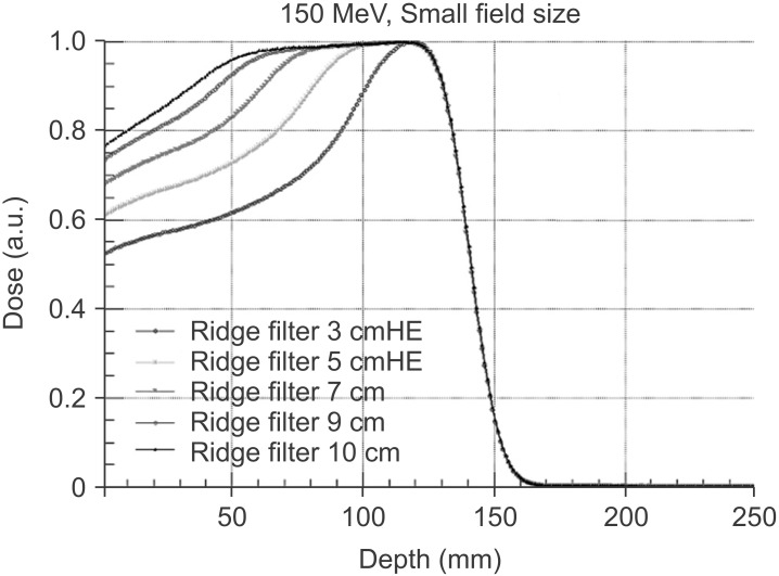
The detailed description of the Monte Carlo modeling of the nozzles using TOPAS is available elsewhere [4]. The main goal of the Monte Carlo modeling of the treatment nozzles is to expedite the commissioning process of the nozzles by interpolating or extrapolating measured beam data with Monte Carlo simulation results. An example of the spread-out Bragg peak (SOBP) curves generated by TOPAS simulation is shown in Fig. 4.
And independently, Monte Carlo modeling of the treatment nozzles have been developed using Geant4 and MCNP. The original purpose in each simulation package was different (e.g., the nozzle model using MCNP was developed to study neutron dose for real time image guided proton therapy [5]) but they can be used as a validation tool for each other.
We will extend applications of developed Monte Carlo simulation models to researches on non-beam performance of the nozzles and design studies of nozzle elements in the future.
Results
1. Status
The installation of proton therapy system has been finished in 2014. Since then, SHI engineers have conducted an intensive machine tuning of the proton therapy system. For a certain period of time, the proton therapy system is under machine commissioning phase and we have planned mock-up treatments as a clinical commissioning of the proton therapy system following the completion of the machine commissioning.
The beam data measurement for the modeling of treatment planning system started in March 2015. SMC has selected RayStation (RaySearch Laboratories AB, Stockholm, Sweden) as proton treatment planning system. RayStation is one of the most advanced proton treatment planning system with distinguished features like, robust optimization, pencil beam algorithm with graphics processing unit (GPU) support, scripting support, robust planning, etc. It will support SHI's beam delivery techniques.
We have been collecting the beam data according to the required beam data list from RaySearch Laboratories AB. The measured beam data will be used for the beam modeling of RayStation.
1) Proton beam specifications including beam penumbra, distal fall-off width, dose uniformity, SOBP width, maximum dose rate, etc.
Based on the early beam data measurements, selected proton beam specifications can be described as following: the maximum range in G1 wobbling nozzle is varying with difference field size configurations (LARGE, MIDDLE, and SMALL) as the optimized total thickness of scatterers depends on the field size. The minimum range in the LARGE field configuration is measured to be 25.7 mm and the maximum range in the SMALL field configuration is measured to be 308.8 mm. The lateral penumbra (80% to 20%) at the middle of SOBP is also a function of the field size, beam energy, and the ridge filter selection. In the beam data measurement set, the minimum value of the lateral penumbra is achieved to 3.26 mm (70 MeV, SMALL, 1 cm ridge filter). The distal fall-off (distal 80% to 20%) is also a function of the beam energy, field size, and the ridge filter selection. The measured distal fall-off values are in the range of 1.2 mm to 6.8 mm. The dose uniformity in the lateral direction has been verified to be within 2% (80% of the field size region). The dose uniformity in the depth direction has less physical meaning as a single physical ridge filter covers a certain energy range: a slight slope in the depth direction cannot be avoided unless it is used with the optimal condition. The average dose rate in G1 wobbling nozzle is verified to be greater than 2 Gy/min for 1-liter volume (above 110 MeV). More detailed dosimetric characteristics of SMC-PTS will be reported in a separate article in the future.
2) Expected patient setup accuracy with the delivered treatment room system
The angular accuracy of gantry rotation is less than 0.2° and the positional accuracy of isocenter of G1 wobbling nozzle is less than 1 mm. The positional accuracy of the robotic couch has been meticulously tested and it is below 1 mm. The laser alignment system has been adjusted to the DR system within 0.2 mm accuracy. The simple quadratic sum of these uncertainties yields a total uncertainty of 1.4 mm and this is a conservative estimation as the correlation among the items has been ignored. In addition to the orthogonal X-ray imaging system, CBCT was integrated in to the gantry, therefore the setup using the internal landmark more relevant to target position will be possible.
For oncology information system, SMC made a choice on MOSAIQ (Elekta AB, Stockholm, Sweden) based on following requirements; support of SHI's beam delivery information, RayStation planning information, SMC Hospital Information System (HIS) and oncology communication, remote access (open network), integration of IGRT for proton, and integrated plan-comparison functionality.
The installation of MOSAIQ system and the first integration test with Sumitomo treatment control system (TCS) have been finished in March 2015. The final integration test among RayStation, MOSAIQ, and Sumitomo TCS will be coming soon.
3) Staffing for running of the proton therapy center
According to the original proton project, there will be 6 physician staff dedicated to the proton therapy at the beginning. The number of medical physicists has been gradually increased up to 10 since the ground breaking. The engineering team has also grown up to 5. In each treatment room, CT simulation room, and the machine shop, 2 radiation therapists will be assigned. One biologist has joined the project and started to work on researches related to the proton therapy.
The volume of staffing will be related to the volume of proton therapy patient as well as the stage of the project. Up to starting of patient treatment, the physicists staff have been gradually increased for beam commission. In the clinical commissioning stage at least two medical doctors dedicates to proton therapy are required.
For therapist, assigning more than 2 radiation therapists for each treatment room is necessary due to the complexity of patient positioning and proton beam delivery.
4) Plan for indications of the proton therapy
At the beginning, focus of the clinical indications of the proton therapy will follow an evidence-based approach: the tumor sites demanding a better dose conformality while the tumor is contiguous to critical structures, pediatric cancers, and so on. The comparison studies with IMRT for all candidate disease sites are currently going on.
Discussion and Conclusion
We have described the SMC-PTS and reviewed the current status of the project overall. Two rotating gantry rooms with a multi-purpose nozzle and a dedicated pencil beam scanning nozzle will be used for the proton beam therapy of cancer patients at SMC-PTS. It will be capable of treating over than 480 new patients per year under 8-hour daily operation.
A clinical commissioning following the machine commissioning will be intensively conducted with mock-up treatments for each clinical case thoroughly and it will guarantee a precise and accurate proton beam treatment at SMC-PTS.
Along with the clinical commissioning, we will measure relative biological effectiveness (RBE) values with various conditions for proton beam at SMC. Although a universal RBE of 1.1 has been widely used in clinical proton beam therapy [6], a recent study indicated that a fixed RBE is not ideal for proton treatment planning [7]. The RBE varies with different parameters such as linear energy transfer, dose per fraction, and tissue type. With the RBE measurement at SMC-PTS, further study of RBE-based proton treatment planning can be carried on.
With all the machine and clinical commissioning, we are working toward a successful launching of the first private-hospital based proton therapy center in Korea on schedule to be operational in 2015.