


Introduction
Many studies have been devoted toward developing methods to administer highly conformal radiation in the targets while minimizing doses to normal tissues and critical organs [1]. Intensity-modulated radiation therapy (IMRT) is the result of such efforts.
IMRT has a much greater potential to shape spatial dose distributions than conventional radiotherapy with uniform beams. This capability has been used to tailor the dose distribution to the tumor target volume in conformal radiotherapy. IMRT is especially advantageous when treating patients with head and neck cancer where the complexity of the anatomy and tumor proximity to many critical and radiation-sensitive tissues makes treatment with conventional methods difficult [1-4].
In the course of IMRT planning, it is common practice to use computed tomography (CT) images, and the CT images used in the course of IMRT planning are still images. Therefore, IMRT planning cannot consider respiratory movement.
However, the human body is in constant repetitive motion due to physiology and respiration. In particular, a tumor located in the chest region will be in regular motion. Also, if there are movements during the delivery of the IMRT (intra-fraction movements), such as respiratory organ motion, dose may not add up to the desired total dose as planned at the target volume [5,6]. In addition, respiratory organ motion can potentially lead to overdoses outside the target volume. As a result, because movement occurs during the delivery of IMRT fields, the delivered intensity and dose map can also be very different from the planned one [6-9].
An American Association of Physicists in Medicine (AAPM) survey shows that 87% of the clinics have implemented IMRT. While 23% of the clinics treat lung tumors with IMRT, only 12% of the clinics have respiration gating equipment. This implies that many clinics treat disease sites affected by respiratory motion without respiration gating equipment. Nowadays commercial 4D computed tomography (4DCT) can be used to determine the internal target volume and design safety margins tailored to individual patients. However, dosimetric errors in the target volume still exist because many IMRT are implemented without respiration management [10].
The purpose of the present study is to investigate the change of dose distribution due to respiratory motion. In this study, we measured 2D dose distributions delivered under realistic clinical conditions. By comparing the calculated dose distribution and the measured dose distribution, we analyzed the change of dose distribution caused by respiratory motion.
Materials and Methods
1. IMRT plans
In this study, we used IMRT plan for esophageal cancer. In the case of esophageal cancer, dose distribution is significantly affected by respiratory motion because target volume is located on the chest. Moreover, because critical organs are located around the target volume, esophageal cancers are sensitive to changes in dose distribution.
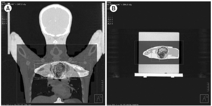
IMRT plans were generated for the phantom using a commercial treatment planning system (TPS; Pinnacle 8.0, Philips Medical System, Andover, MA, USA). An in-house motion phantom was scanned in helical mode on a GE multislice CT scanner (Ultra Lightspeed 16, General Electric Medical System, Waukesha, WI, USA). After the completion of the scan, the CT images of phantom were exported to TPS. We copied the existing IMRT plan for esophageal cancer to the CT images of phantom, and calculated the dose distribution. This dose distribution is the result in state without the respiratory motion (radiotherapy treatment planning, RTP). Fig. 1 shows a screen of TPS.
2. Modeling of respiratory patterns
The respiratory patterns between patients seem to widely differ. Therefore, three most commonly observed respiratory motions were modeled for the purpose of this experiment. In this study, the results of Anthony E. Lujan et al.'s study were used in respiratory modeling [11]. The following mathematical model that describes respiratory motion.

In this equation Z(t) is the position at exhale, b is the extent (amplitude) of the motion, Z0-b is the position at inhale, τ is the period of breathing cycle, n is a parameter that determines general shape (steepness and flatness) of the model, and φ is the starting phase of the breathing cycle.
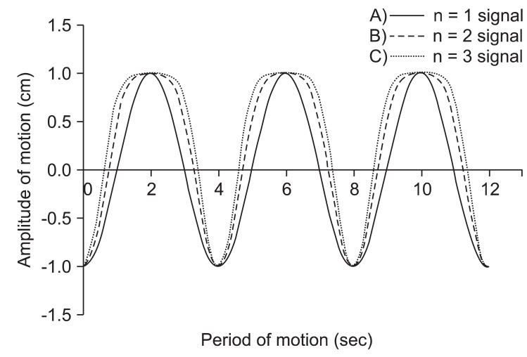
In this study, we used a period for the breathing cycle τ = 4.0 seconds, an extent of motion b = 2.0 cm, and a value of n = 1, 2, and 3. The first respiratory pattern is 'even inhale-exhale pattern'. In this case, a parameter (n) that determines general shape of the model is one (n = 1 signal). The second respiratory pattern is 'slightly long exhale pattern' (0.35 seconds longer than inhale period). In this case, the value of n is two (n = 2 signal) and this respiratory pattern is most commonly respiratory pattern. The last respiratory pattern is 'long exhale pattern' (0.7 seconds longer than inhale period). In this case, the value of n is three (n = 3 signal) [11,12]. Fig. 2 shows the respiratory signal for the three patterns. These respiratory patterns (n = 1 signal, n = 2 signal, n = 3 signal) were used to simulate phantom motion.
3. Motion phantom
An in-house motion phantom was used for the study. The motion phantom consists of a motor for respiratory motion, a phantom holder for a fixing, and solid water phantom for film dosimetry. The motion phantom can move in the one dimension (cranial-caudal direction). Fig. 3 shows the 2D rendering of the each structure.
The motion pattern of phantom, the amplitude and period as well as inhale-exhale period, can be controlled by in-house developed software (LabVIEW 7.0, National Instruments, Austin, TX, USA). This software creates the motion of phantom the same as the input respiratory signal from equation 1.
4. Phantom study
As mentioned above, IMRT mock treatment was performed four times using the motion phantom. The different respiratory patterns for each treatment were used to generate motion. In the first mock treatment, we used 'the state of stopped breathing'. In other words, phantom is a state that motion is stopped (static). The respiratory signal used in the second mock treatment is 'even inhale-exhale pattern' (n = 1 signal). In the third and fourth mock treatment, 'slightly long exhale pattern' (n = 2 signal) and 'long exhale pattern' (n = 3 signal) were used.
To simulate IMRT mock treatment, a linear accelerator (6EX, Varian Medical Systems, Palo Alto, CA, USA) was used in this study. The Kodak EDR2 film (Eastman Kodak Company, Rochester, NY, USA) was placed between the solid water phantoms to verify the dose distribution of each IMRT mock treatment. A exposed EDR2 film was scanned using a film digitizer (Vidar VXR-16, Vidar Systems Corporation, Herndon, VA, USA), and a dose distribution of each IMRT mock treatment was calculated using a analysis software (RIT 113, Radiological Imaging Technology, Colorado Springs, CO, USA).
In this study, we used two kinds of analytical methods. In the one method, dose curve (1D) passing through the center of the target volume was used. In another method, the dose distribution (2D) passing through the center of the target volume on the coronal plane was used. The dose distributions were analyzed using gamma index (3%, 3 mm).
Results
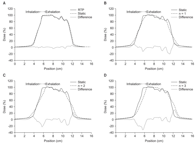
Fig. 4 shows the one-dimension dose curve passing through the center of target volume. In Fig. 4, the direction of curve is the cranial-caudal direction, X-axis is position in the cranial-caudal direction, and y-axis is dose at the each position.
We compared the results (RTP) of calculation by TPS and the results (static) of measurement in 'the state of stopped breathing' (Fig. 4A). In Fig. 4A, the two curves are well matched both in the target volume and at the boundary of the target volume.
On the other hand, the differences between the results (RTP) of calculation and the results (n = 1 signal) of measurement in 'even inhale-exhale pattern' were found to be considerable at the boundary region of the target volume, and the area meeting prescription doses inside the target volume was reduced. Also, the size of penumbra was increased to out of both boundaries.
In comparing 'the state of stopped breathing' (static) and 'even inhale-exhale pattern' (n = 1 signal), maximum 5% in the target and maximum 20% dose differences at the boundary of the target were observed. Also, the isodose-points in 90% of prescription dose at the boundary of the target moved approximately 3.5 mm in the direction of inside target volume. The isodose-points in 10% of prescription dose moved approximately 6 mm in an outward direction. As a result, the length (area) of prescription dose was decreased from 5.44 cm to 4.7 cm.
In Fig. 4C and 4D, we confirmed that the dose difference at the boundary of the target volume increased to a maximum 30% depending on the increase of expiratory movement. Also, both the isodose-point (90% of prescription dose) and the center of high-dose area inside target volume were moved toward the cranial direction. But, the length (area) of prescription dose remained largely unchanged (about 4.7 cm).
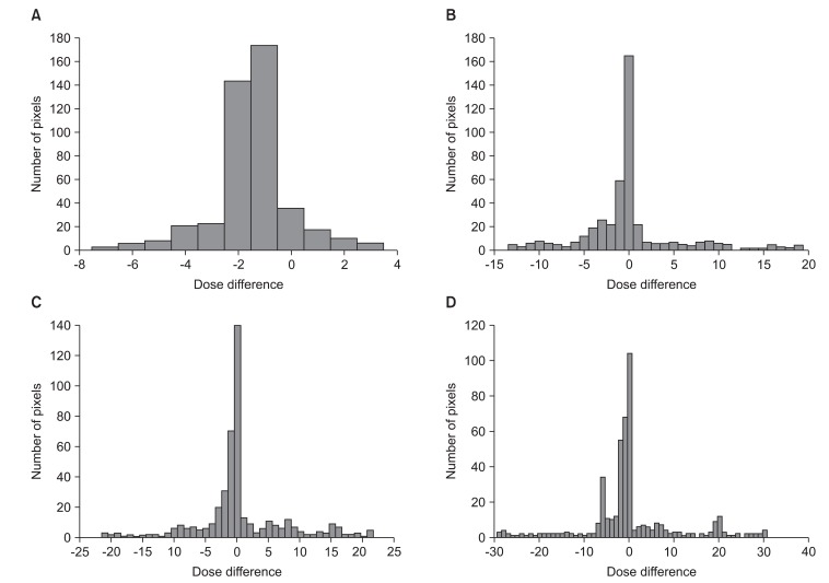
Fig. 5 shows through a histogram of number of pixels, the dose differences between (A) RTP and static, (B) static and n = 1 signal, (C) static and n = 2 signal, (D) static and n = 3 signal. In the case of static, 89% of the entire pixels were consistent with a margin of error of less than ±3% (Fig. 5A). The n = 1 signal was 64% (Fig. 5B), n = 2 signal 62% (Fig. 5C), and n = 3 signal 55.2% (Fig. 5D). As shown by the results, the matching percentage of pixels with less than a ±3% margin of error reduced more and more.
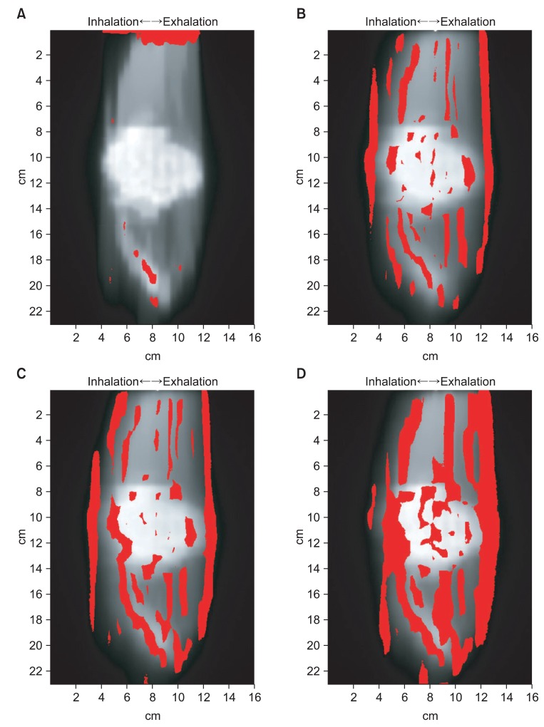
We compared the two-dimensional dose distribution by gamma index (3%, 3 mm) (Fig. 6). In Fig. 6, the red area indicates where the gamma index greater than 1. In 'the state of stopped breathing' (static), the area of gamma index greater than 1 was 2.09%. And the area of gamma index greater than 1 were 11.88%, 15.11%, and 24.33% for 'even inhale-exhale pattern' (n = 1 signal), 'slightly long exhale pattern' (n = 2 signal) and 'long exhale pattern' (n = 3 signal), respectively. The long exhale pattern showed largest amount of error (Table 1).
Discussion and Conclusion
To verify the accuracy of plan and measurement used in this study, we were compared the results (RTP) of calculation and the results (static) of measurement (Figs. 4A, 5A, 6A, Table 1). As a result, the two results were the same. Therefore, we were able to verify the accuracy of calculation and measurement for IMRT.
On the other hand, we observed change of dose distribution caused by respiratory motion. The pattern of change is independent to motion distance (amplitude) and is dependent to respiratory pattern (length of expiratory). In other words, the under-dose area in target volume and the over-dose area around target increased together with the increase of the expiratory period compared to inspiratory period.
These results are caused by two reasons. First is an increase in penumbra. In Fig. 4B, the length of prescription dose in target volume is decreased and the length of low dose at the around target is increased. An increase in penumbra by respiratory motion was reported by Cuijpers et al. [13]. It was demonstrated that the penumbra by respiratory motion is proportional to amplitude using time weighted 4DCT images.
But, despite the increase in time of expiratory, dose curve shape was similar. Fig. 4B-4D shows that the length of 50% in dose curve was the same. And the length of 85% in dose curve was very similar. Therefore, the increasing dose change represented in Fig. 6B-6D is caused by a phenomenon of dose accumulation rather than a increase in penumbra by respiratory motion. Due to a phenomenon of dose accumulation, the center of high-dose area moved in the cranial direction. Because of this, low-dose was irradiated to caudal direction in target volume, and high-dose was irradiated to cranial direction at the around target.
In the most commonly observed respiration pattern for patients, the target is not moved during a specific time in the expiratory position. At this time, the dose is cumulative to target at the expiratory position. But, the dose is not cumulative to target at the inspiratory position because target is continuously moved. Thus, the change of dose distribution in the treatment of moving target was caused by two reasons. The first reason is a penumbra. Penumbra increases in proportion to the amplitude of respiration. The other reason is the movement of high-dose area due to a phenomenon of dose accumulation at the expiratory position.
The most common phenomenon observed in the treatment of a moving target is an averaging out of dose distribution in the target volume (Fig. 5B-5D). This phenomenon of dose distribution in target volume is a deductive factor and should be seriously considered in IMRT. The averaging of dose distribution in target volume is well described in the study by Bortfeld et al. [14]. Bortfeld et al. [14] showed an averaging of dose distribution in IMRT using a statistical model.
An over-dose at the around target causes complications in normal tissue. And low-dose in target volume has negative implications in treatment results. These phenomenons should be seriously considered and factored into treatments at high prescription doses (stereotactic body radiation therapy etc.). Therefore, respiratory pattern should be taken into consideration in chest and abdomen IMRT if dose distribution and the treatment results are to improve.
We believe that there are two ways to reduce dose error. One method is to keep respiratory amplitude as minimal as possible. This will minimize the area of penumbra at the around target. Another way is to educate patients to keep an even inhale-exhale period. This will minimize the moving of center in high-dose area.
This study is limited in that organ motion due to breathing is assumed to be one dimensional in the cranial-caudal direction. Therefore, the changing of dose distribution in this study and the changing in the real treatment are different. However, when considering that the cranial-caudal direction is the dominant movement, we believe that the changing pattern of dose distribution is a relatively accurate portrayal of reality.